Instrument Descriptions
Instrument Numbers And Descriptions
Current as of firmware release 1.06.
The instrument number is used with the inst CLI setting to select which instruments are displayed on a screen and what order. You can assign up to 12 instruments per screen on the 3.5 inch and 4 inch screens, 6 instruments on the 2 inch to 3.2 inch screens, and different numbers on smaller screens.
You can have multiple instrument pages that can be changed in flight. If your display shows 6 instruments, you will have 2 different pages. If your screen can show 4 instruments, you will have 3 different pages.
Images are captured directly from the screen buffer on the controller.
Sample Panel Layouts
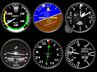
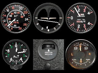
Sample panel layouts are completely configurable.
320 x 240 Screens
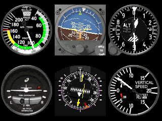
480 x 320 Screens
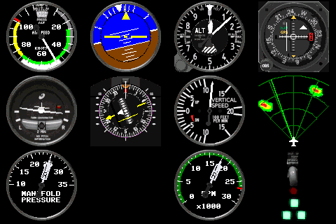
1) Airspeed Indicator
Speed data comes from either GPS ground speed or pitot airspeed. Pitot airspeed is selected using the CLI pitot command. Speed can be displayed in knots or kph using the CLI units command. V-speeds are set using the CLI vspeeds command.
MSP data: MSP_RAW_GPS or MSP2_INAV_AIR_SPEED
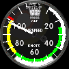
2) Attitude Indicator
Attitude data comes from flight controller roll and pitch.
MSP data: MSP_ATTITUDE
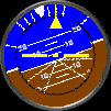
3) Altimeter
Altitude data is received from the flight controller estimated position or from the barometer. Barometer altitude is selected with the CLI baro command. Altitude can be displayed in feet or meters using the units command.
MSP data: MSP_ALTITUDE
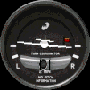
4) Turn Bank Indicator
The bank indicator uses data from the gyro. The slip indicator uses the accelerometer.
MSP data: MSP_RAW_IMU
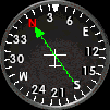
5) Directional Gyro With RMI
Direction uses the attitude yaw setting. RMI points to Home, which is the armed location.
MSP data: MSP_ATTITUDE, MSP_COMP_GPS
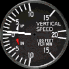
6) Vertical Speed Indicator
Vertical velocity is received from the flight controller. VSI is shown in feet per minute.
MSP data: MSP_ALTITUDE
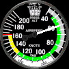
7) Airspeed Indicator Alt
Speed data comes from either GPS ground speed or pitot airspeed. Pitot airspeed is selected using the CLI pitot command. Speed can be displayed in knots or kph using the units command. V-speeds are part of the background and are not currently settable.
MSP data: MSP_RAW_GPS or MSP2_INAV_AIR_SPEED
8) Attitude Indicator Electric
Attitude data comes from flight controller roll and pitch.
MSP data: MSP_ATTITUDE
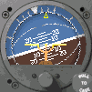
9) HSI
Direction uses the attitude yaw setting. The CDI uses the selected waypoint or runway and the HSI radio channel to set the desired course. The radio channel is selected with the hsirc command, which defaults to channel 10.
Waypoints can be set with the waypoint command and runways with the runway command.
MSP data: MSP_ATTITUDE, MSP_COMP_GPS, MSP_RAW_GPS, MSP_ALTITUDE
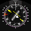
10) RMI
Direction uses the attitude yaw setting. RMI points to Home, which is the armed location.
MSP data: MSP_ATTITUDE, MSP_COMP_GPS, MSP_RAW_GPS
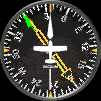
11) VOR
Uses programmed waypoints and runways to set CDI and glideslope.
MSP data: MSP_RAW_GPS, MSP_ALTITUDE
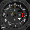
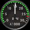
12) Tachometer – Single Engine Or Left Engine
13) Tachometer – Right Engine
Shows the RPM received from the ESC. ESCs must each be on their own output from the flight controller, and the left engine is assumed to be the first ESC.
MSP data: MSP2_INAV_ESC_RPM
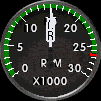
14) Tachometer Twin Engine
Shows left and right RPMs.
MSP data: MSP2_INAV_ESC_RPM
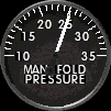
15) Manifold Pressure – Single Engine Or Left Engine
16) Manifold Pressure – Right Engine
Pressure is displayed based on the servo signal sent to the motors. If the same signal is always sent to both motors on a twin, both needles will move together. If your plane is set up for differential thrust, it will show separate readings. The left engine is assumed to be the first motor signal.
MSP data: MSP_MOTOR
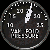
17) Manifold Pressure – Twin
Shows both needles.
MSP data: MSP_MOTOR
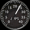
18) Fuel Flow – Amps
Amps are the overall amperage draw detected by the flight controller. There is not a way to get individual current draw on two ESCs.
MSP data: MSP_ANALOG
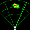
19) Weather Radar
Displays simulated weather.
MSP data: MSP_ATTITUDE, MSP_RAW_GPS or MSP2_INAV_AIR_SPEED
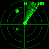
20) Aircraft Radar
Displays simulated targets. Targets will chase, track, and fire missiles. iNav 8.1 will support ESP32 Radar and display real data. ADS-B data support is planned.
MSP data: MSP_ATTITUDE, MSP_RAW_GPS or MSP2_INAV_AIR_SPEED
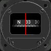
21) Compass
Displays heading in a whiskey compass format.
MSP data: MSP_ATTITUDE
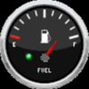
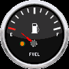
22) Fuel Gauge
Displays percentage of battery remaining.
MSP data: MSP2_INAV_ANALOG
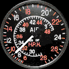
23) RAF Airspeed
WW2 RAF airspeed indicator.
MSP data: MSP_RAW_GPS or MSP2_INAV_AIR_SPEED
24) RAF Attitude
WW2 RAF attitude indicator.
MSP data: MSP_ATTITUDE

25) RAF VSI
WW2 RAF vertical speed indicator.
MSP data: MSP_ALTITUDE
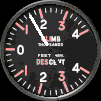
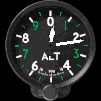
26) RAF Altimeter
WW2 RAF altimeter.
MSP data: MSP_ALTITUDE
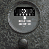
27) RAF Compass
WW2 RAF compass.
MSP data: MSP_ATTITUDE
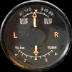
28) RAF Turn/Bank
WW2 RAF turn/bank indicator.
MSP data: MSP_RAW_IMU
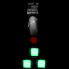
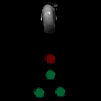
29) Gear Indicator
Shows the position of gear based on a selectable servo channel.
MSP data: MSP_RC
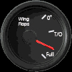
30) Flap Indicator
Shows the position of flaps based on a selectable servo channel.
MSP data: MSP_RC