
Cockpit Gauges
Integrated avionics displays for immersive FPV aircraft cockpits.
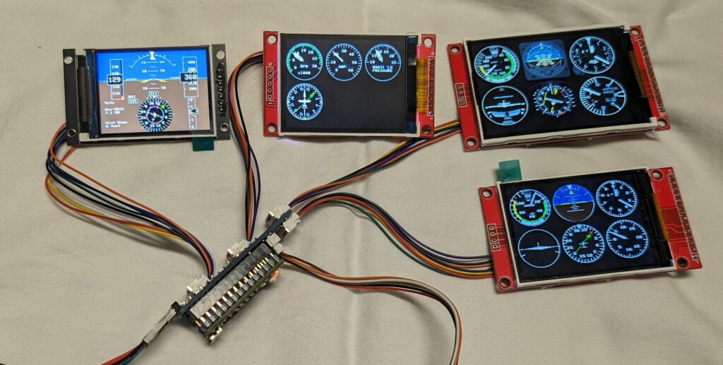
The FPVToys cockpit system is a modular avionics platform designed for RC aircraft and FPV cockpits. A single avionics controller can drive up to four independent displays, providing realistic flight instrumentation, navigation, telemetry, and moving-map functionality.
The FPVToys avionics controller supports multiple telemetry protocols, including MSP, MAVLink, and SmartPort. Telemetry data such as GPS position, navigation information, aircraft attitude, airspeed, altitude, and ADS-B traffic data are received through a compatible flight controller using one of these supported protocols. Simulator functions and in-flight display control can also be operated through SBUS or assigned radio-control channels. iNav is currently required for RPM sensor support.
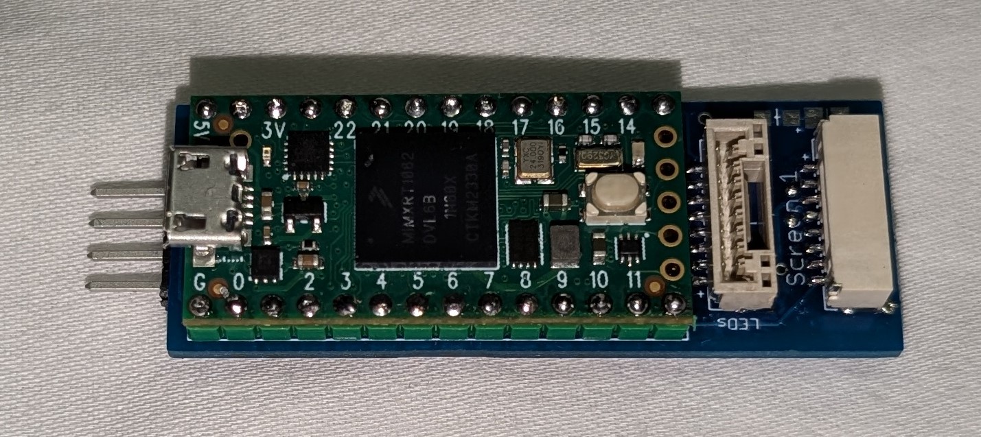
The controller will drive up to 4 displays at the same time. The displays range in size from 0.7″ to 4″ and resolutions from 128×128 to 480×320.
Telemetry is supplied through a compatible flight controller using one of the supported protocols. Power wiring depends on the controller and display setup.
Supported instruments include:
- Attitude indicator
- Airspeed
- Altimeter
- Turn / bank
- Vertical speed
- Directional gyro
- HSI – localizer and glideslope
- RMI
- RPM (single or twin)
- Amps
- Manifold pressure (throttle position)
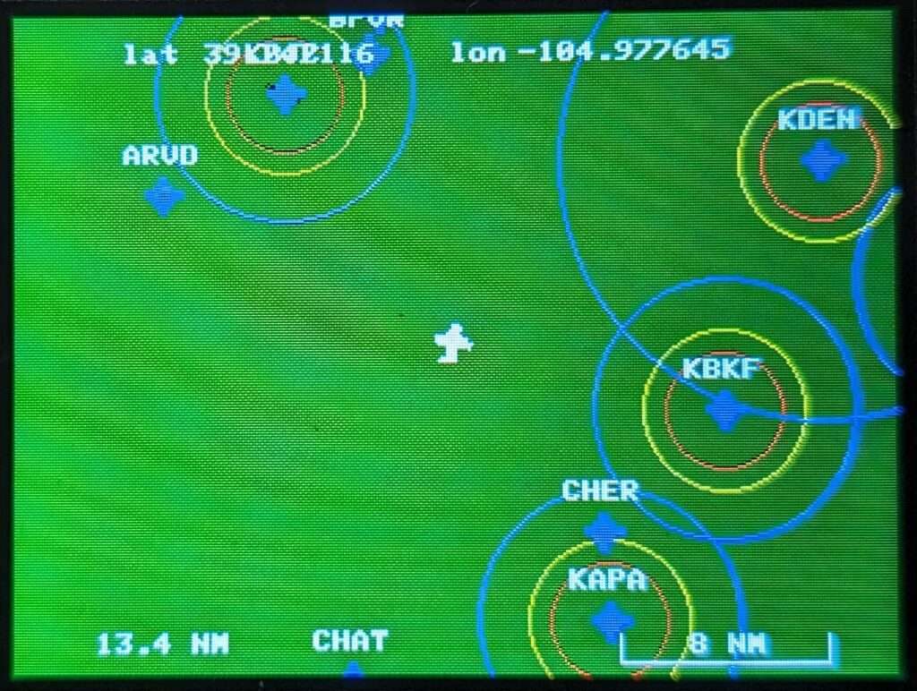
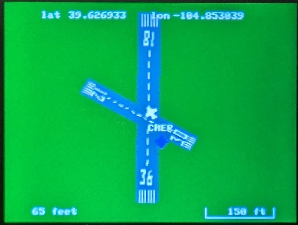
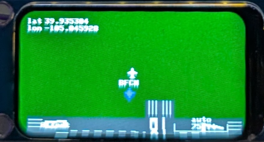
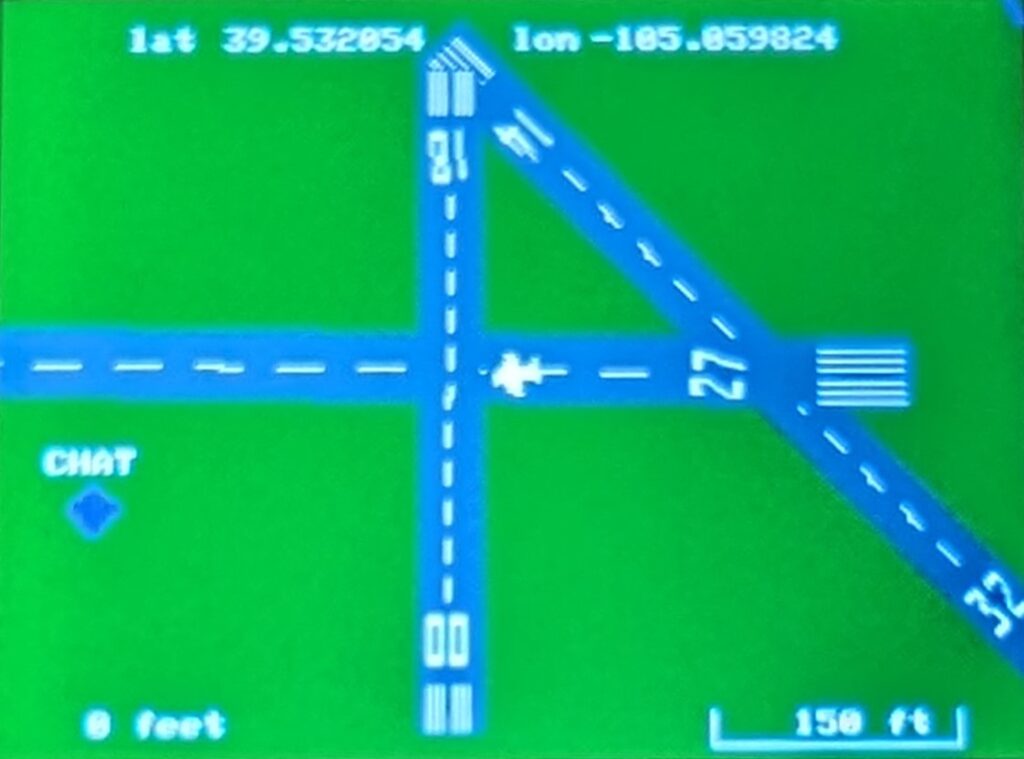
Moving Map
Integrated moving-map avionics provide real-time runway, waypoint, and airport visualization directly within the cockpit display system.
Navigation Lights
With the optional navigation light board and LEDs, you can add lighting to your plane. This is similar to the Navigation Light Controller (that plugs into a servo port), except this one is run from the Gauge Controller board.
Flight Simulator Mode
The controller has a simulator built in and can be turned on and off (turn off before flying). Simulator needs a flight controller hooked up to send data to it. Moving the flight controller will show roll, pitch and yaw on the displays. Pitching up will slow the airspeed down and increase the altitude. Pitching down will do the opposite.
If a radio is connected to the flight controller, it will take the commands from the radio and you can fly around the map.
The simulator is enabled from the CLI.
Controllable from your radio
Through the CLI, you can set 2 channels from your radio to control the displays. The servo channels do not have to have physical ports on the flight controller, the signals come through the serial port.
1) RC analog channel can be used to select the HSI course to a waypoint or runway. If you select a runway and a course that is within 10 degrees of either end, it will lock onto it and become an ILS, with localizer and glideslope (default 3 degrees, but can be configured in the CLI)
2) RC channel used to simulate button presses and set the nav lights.
Sending the following values will make the controller do the following:
| Channel value | Action |
|---|---|
| 900 uS | Nav lights off |
| 1000 uS | Position/beacon lights on |
| 1500 uS | + Strobes on |
| 2000 uS | + Landing lights |
| 1100 uS | Previous VOR/airport |
| 1200 uS | Select previous display (if you have more than 1) |
| 1300 uS | Mode up |
| 1400 uS | Map zoom in |
| 1600 uS | Map zoom out |
| 1700 uS | Mode down |
| 1800 uS | Select next display |
| 1900 uS | Next VOR/airport |
CLI Configuration
Display driver and resolution can be selected, and the image can be flipped or mirrored so it can be installed the most convenient way. Colors can also be inverted when required.
Each display can show one of 4 modes (G1000, moving map, instrument 1, instrument 2), and display selection can be changed from the radio during flight.
The instrument displays can be configured to show up to 6 instruments from a selection of 16. The two instrument displays each have their own layout, and each display has its own instrument layouts. 6 instruments can only fit on displays that are 320 pixels wide; other displays can only show 4.
You can enter waypoints for the moving map. These can be a model airfield, class B, C, D, and uncontrolled airports, and virtual VORs.
Airports will display their airspace on the map. For class B, C, and D airports, the display will flash Airspace when inside it.
It will also display a yellow ring where the ceiling is 100 feet and a red ring where the ceiling is 0 feet. (These two circles are approximate because those limits are unique for every airport).
Runways can be entered and will be displayed on the map. These can be any runway: real, model, or virtual (like a park).
Airports and waypoints can also be generated using the Airport / Waypoint Tool and then entered through the CLI.