
CLI commands
Using CLI commands
Setting up
Use a terminal program such as Tera Term or Putty on windows or iTerm2 on mac.
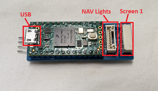
The microcontroller has a native USB controller, so it will work with any speed and data format.
The connector on the board is a micro USB plug
When the controller is plugged in, the computer should create a new serial port.
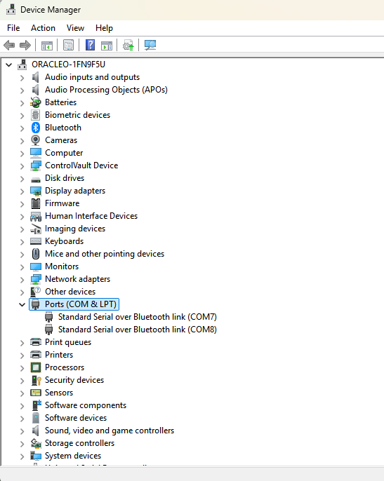
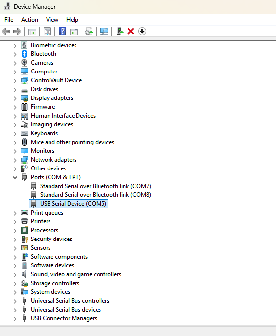
On Windows, If you are having trouble figuring out what port it is, open up the Device Manager
Expand the Ports entry and see what COM ports are available. Plug in the controller and see what new USB Serial Device shows up (below it's COM5).
This is the port you open to talk to the controller.
Plug in screens and USB cable

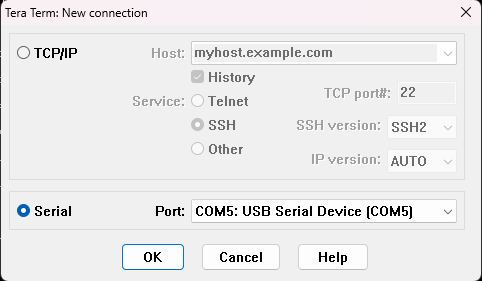
Open terminal program and select the serial port the controller is on
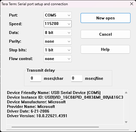
Tera Term settings (select the COM port that shows up when the controller is plugged in)
If you are already running Tera Term, you can change the serial port settings by selecting: Setup -> Serial Port...
Adjust settings for screens
Starting with screen 1
Make sure the correct drive is selected.
Select the driver based on the screen resolution.
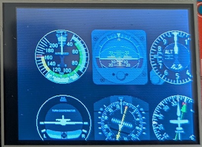
For the 320x240 screens, there are 2 drivers to select from (3 & 4). Select the one that properly draws the screen.
The 2" screens by default have the colors inverted, use the invert command to correct it.
Use the mode command to select what to display on the screen.
Use flip / rotate / mirror to adjust the image
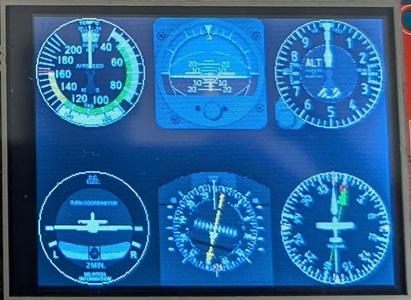
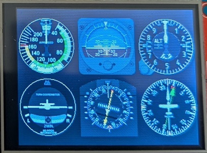
If you are displaying instruments, use the inst command to select which ones are displayed.
If using more than 1 screen, use the screen command to select another screen and repeat the above instructions for each one.
Use the other commands to make adjustments to the system.
List of cli commands
? or help
Shows list of command with a brief description (firmware version introduced)
command followed by ? or help will display more details
* help
Print list of commands
* ?
enter '<command> ?' for more help
* settings
display current settings
* input
select source of data input (m/v/p/i/s/r).
* uart
select uart speed to communicate with flight controller.
* screen
screen <#> - set screen to configure
* driver
driver <#> - sets the driver for screen
* invert
inverts display colors
* flip
rotate display 180 degrees
* rotate
rotate <#> - rotate display 90 degrees
* mirror
mirror display
* mode
what each screen displays. type 'mode ?' for more info
* inst
select which instruments will be displayed and what locations
* mfd
mfd layout
* layout
spacing for steam gauges
* xoffset
xoffset <#> number of pixels to move image on x axis (+/- 127) for steam gauges
* yoffset
yoffset <#> number of pixels to move image on y axis (+/- 127) for steam gauges
* enable
enable <g/m/w/a/p/f/r/h/u/s/i> - screens to scroll through. 'enable gmwapfri' enables all
* logo
logo <f/g/a/c/b/r> - set the boot screen logo
* scale
scale <on/off> scale down steam gauges on displays the show 3 or less instruments
* zoom
zoom <+/-/a> map zoom level, a = auto
* drawdelay
drawdelay <ms> - delay in ms after drawing screen (if part of next screen is seen when updating)
* units
<f/m/c> sets units to f)eet/Knots/Nautical miles, m)eters/kilometers or c)ombo metric w/altitude in feet
* rpm
set max rpm (x1000) on tachometer. ie - 30 = 30,000
* altitude
set altitude type: a)AGL, m)MSL
* amps
set max amps on amp gauges
* airspeed
set airspeed scale (100 = 100%)
* hsirc
hsirc <#> - radio channel # for adjusting hsi
* buttonsrc
buttonsrc <#> - radio channel # for buttons
* gear
gear <#> - radio channel # for gear indicator
* flaps
flaps <#> - radio channel # for flap indicator
* vspeeds
display current vspeeds
* glideslope
Set glide slope for ILS approaches
* pitot
Use pitot for airspeed
* baro
Use baro for altitude
* led
board led (on/off)
* navled
navled <b/l/n/s/m/o> - alternate led function
* planes
planes s)sim a)ADS-B e)ESP32-radar / formation flight
* bandit
set speed (knots) and turn rate (degree/sec) of bandit aircraft
* onmap
display planes on map
* delay
boot delay in seconds (show boot screens)
* map
display map data waypoints (airports, vor, etc.)
* waypoint
Set waypoints for map
* airport
Set airports for map
* runway
Set runways for map
* home
Set home location
* loadFcWaypoints
(on/off) - Load waypoints saved in flight controller
* sim
turn on/off simulator
* hidegps
hide GPS coordinates
* version
list version info
* dump
dump settings to copy/paste
* save
Save settings
* reboot
Reboot the module (no save)
* capture
capture bitmap of current screen
settings
Display invert/mirror
# driver res | rot mode instrument layout
------------------------------------------------------------------
1 4 ILI9341 320x240 1 g G1000 a{1,2,3,4,5,6} b{7,8,9,10,11,12}
2 2 ST7789 280x240 i 3 d Debug a{1,2,3,4} b{5,6,7,8} c{3,4,9,6}
3 0 None
4 0 None
Input: m) MSP
VSpeeds: VFlap VF_End VNorm VCaut VNe
10 40 25 75 101
Units: f) Feet/Miles
Max RPM: 30 (30,000)
Airspeed scale: 100%
Board LED: on
Glide slope: 3.00
HSI channel: 10
Gear channel: 6
Switch channel: 8
Airspeed source: GPS
Altitude source: GPS
Load fc waypoints: off
Flight Controller: iNav
Simulator: off
Firmware Version 1.07
Build Date & Time Feb 17 2025 22:31:17
Settings:0107 Map data:0100
Sold by fpvtoys.net
input (1.05)
Input description
input <m/v/p/i/s/r>
m MSP
v Mavlink
p smartPort
i Inverted smartPort
s sBus
r R/C
uart (1.10)
set uart speed to flight controller (MSP or mavlink)
0) 115200*
1) 57600
2) 230400
3) 460800
4) 921600
5) 1000000
6) 1500000
* selected
screen
Selects screen to make adjustments to. Some commands modify screen settings and this is used to select the screen
ex: >screen 2
 |
 |
driver
Change driver/resolution for selected screen
0) None
1) ST7789 240x240
2) ST7789 280x240
3) ST7789 320x240
4) ILI9341 320x240
5) ILI9488 480x320
6) ST7735 128x128
7) ST7735 160x80
8) ST7789 320x170(172)
9) GC9A01A 240x240
10) GC9D01N 160x160
invert
Invert the colors on the screen
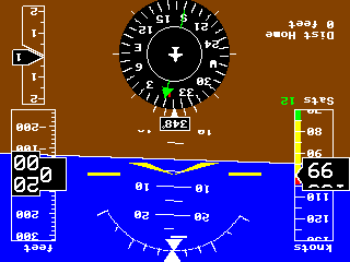
flip
Flips screen 180 degrees. Can also use 'flip <screen num>'
rotate
rotates screen 90 degrees. Can also use 'rotate <screen num>'

mirror
Mirrors screen. Can also use 'mirror <screen num>'

mode
Mode - what the screen displays
Description of modes
'mode' will display the current mode for the current screen
'mode <mode>' will select mode for current screen
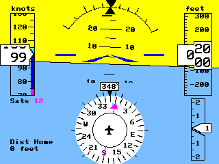
g) G500/G1000 - Primary flight display
m) Map - moving map
w) Weather radar
a) Airplane radar
p) Airline Primary Flight Display
f) Flight Management Computer
r) Radio Stack. Follow by number 0,1, or 2 to select different stacks
h) Heads Up Display
u) Multifunction Display
s) Split Screen showing G1000 and Map
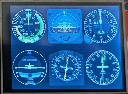
i) Flight Instruments* (Steam gauges)
*i followed by letter (a,b,c,..) can be used to select which set of gauges (see 'inst help' for more info)
' mode i b' will select 2nd instrument screen, i c will select 3rd (if screen displays 4 or less instruments)
d) debug screen (displays what is going on inside)
+) next mode (mode + & - are used to simulate radio mode changes)
-) previous mode
inst
Instrument layout for steam gauges
Instrument Descriptions
Layout position start in upper left and move right then down
1 2 3 1 2 1 2
4 5 6 3 4 3 4
5 6
ex: inst 1 2 3 4 5 6 - standard 6 pack
0 will skip a location, -1 will mark end
changing screens will show the next set of instruments
for screens that can show more than 1 set of instruments, use letters to identify which screen
ex: inst b 1 2 3 4 5 6 - will set instruments for 2nd steam screen
-1 - end of instruments
0 - empty
1 - airspeed
2 - attitude
3 - altimeter
4 - turn coordinator
5 - directional gyro
6 - vsi
7 - airspeed alt
8 - attitude electric
9 - HSI
10 - RMI
11 - VOR
12 - Tachometer single (left)
13 - Tachometer right
14 - Tachometer twin
15 - Manifold single/left (motor RC signal)
16 - Manifold right
17 - Manifold twin
18 - Fuel flow (amps)
19 - Weather Radar
20 - Aircraft Radar
21 - Compass
22 - Fuel
23 - RAF Airspeed
24 - RAF Attitude
25 - RAF VSI
26 - RAF Altimeter
27 - RAF Compass
28 - RAF Turn/Bank
29 - Gear
mfd (1.09)
MFD gauge positions
Layout position start in upper left and move right then down
1 2
3 4
0 - empty
1 - RPM
2 - Manifold Pressure
3 - Fuel Flow - Amps
4 - Fuel Gauge
5 - Horiz Graph
6 - Vert Graph
layout (1.02)
sets spacing for instrument (steam) gauges
layout (p/s/c)
proportional - screen divided into segments and instrument placed in center of each
spread - instruments spread as far apart as possible
centered - instruments grouped into center of screen
 |
 |
 |
| proportional | spread | centered |
xoffset (1.02)
Set screen offset of x axis for steam gauges (+/- 127)
xoffset <#> (+/- 127) number of pixels to shift screen for steam gauges
yoffset (1.02)
Set screen offset of y axis for steam gauges (+/- 127)
yoffset <#> (+/- 127) number of pixels to shift screen for steam gauges
 |
 |
| x and y offsets both positive | x and y offsets both negative |
enable (1.03)
enable modes that can be scrolled through on a screen
screens can be enabled one at a time or in batches
'enable gmwapfri' to add screens or 'enable -gmwapfri' to remove screens
'enable all' to add all, or 'enable -all' to remove all
this is a per screen setting
ex- 'enable gmi' will enable G1000, Map and Instruments
screen 1 modes enabled: gmwapfri
+g) G1000
+m) Map
+w) Weather Radar
+a) Aircraft Radar
+p) PFD
+f) FMC
+r) Radio Stack
+i) Instruments
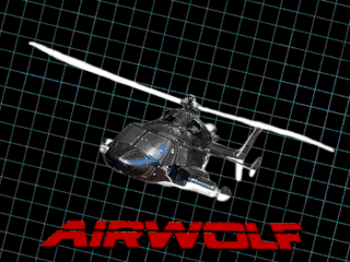
logo (1.03)
set the boot screen logo (they get automatically set based on the mode, but can then be changed)
f) fpvtoys
g) garmin
a) airwolf
c) airwolf w/copter
b) boeing
r) airbus


![]()

scale (1.04)
scales instruments on screen.
Screens that normally only display 3 or less instruments will scale them down to fit more.
Screens that normally display 4 or more will scale them up to only display 1
zoom (1.12)
set map zoom level on individual screen
+ zoom in
- zoom out
a auto zoom
drawdelay (1.12)
delay in ms after drawing a screen.
With simultaneous processing and drawing, there is no delay between screens drawing.
Some screens are slower to release their select pin, causing part of the next screen to be seen at top of display
Adding delay of 3-5 mS should fix drawing. This is usually seen only on 4" displays
units
units <f/m/c> - sets units to f)eet/Knots/Nautical miles, m)eters/kilometers or c)ombo metric w/altitude in feet
rpm
set max RPM displayed on Tachometer in 1000 units. 30 = 30,000
altitude
altitude type a)AGL, m)MSL
MSL only available for GPS
amps (1.09)
set max APMs displayed on Amps gauges
airspeed (1.06)
set scale factor for displaying airspeed (ie - 200 will display 200 kts when reading 100 kts from flight controller)
hsirc
hsirc <channel> - rc analog channel used to set HSI course
hsirc 0 - to turn off
buttonsrc
buttonrc <channel> - rc channel used to simulate button presses & light setting
buttonrc 0 - to turn off
Instructions for setting up radio buttons
900 uS - nav lights off
1000 uS - position/beacon lights on
1500 uS - + strobes
2000 uS - + landing lights
1100 uS - select previous vor/airport
1200 uS - select previous display
1300 uS - change mode
1400 uS - map zoom in
1600 uS - map zoom out
1700 uS - change mode
1800 uS - select next display
1900 uS - select next vor/airport
gear (1.06)
gear <channel> - rc analog channel used for gear indicator (use -channel to reverse operation)
gear 0 - turn off
flaps (1.08)
flaps <channel> - rc analog channel used for flap indicator (use -channel to reverse operation)
flaps 0 - turn off
vspeeds
vspeeds <vflap> <vnorm> <vcaut> <vne> - set vspeeds in knots
example: vspeeds 20 40 70 90
glideslope
Sets the glide slope angle for approaches
pitot (1.01)
Use pitot for airspeed
pitot 0/1
baro (1.01)
Use baro for altitude
baro 0/1
led
Sets the board led on or off
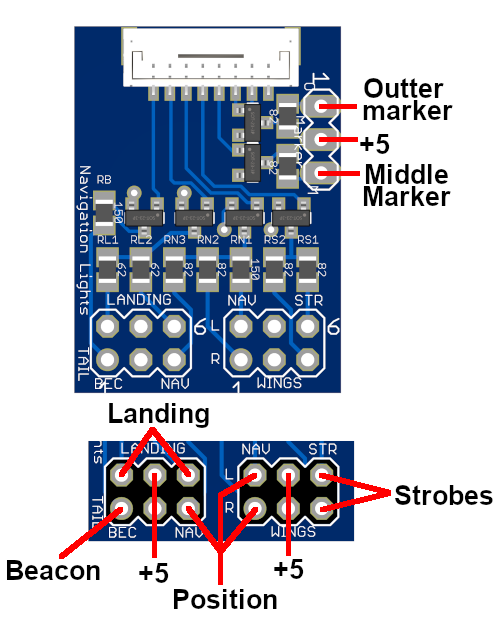
navled (1.08)
Sets the alternate function for LEDs on the nav light board.
nav leds enabled:
+ selects nav light, - selects alternate function
-b) Beacon / *Flaps up
-l) Landing / *Flaps down
-n) Nav / *Gear down
-s) Strobe / *Gear unsafe
-m) Middle Marker / *Flaps down
-o) Outer Marker / *Gear down
| Standard Functions | Alternate Functions |
 |
 |
planes (1.12)
set type of plane to be displayed on radar and map
s simulated
a ADS-B (need receiver)
e ESP32-radar / Formation Flight (need hardware)
bandit (1.12)
set speed and turn rate of bandit aircraft
<entry #> <speed in knots> <turn rate degree/sec>
ex- 1 100 12
set speed to 0 to disable plane
bandit clear to clear all
bandit default set to default
onmap (1.12)
displays other planes on moving map. Show direction and altitude difference in 100s of feet
delay (1.10)
set delay time in seconds to display boot screens
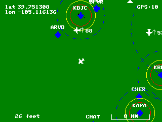
map
displays waypoints/runways that will be drawn on map
map save - saves current map settings
map clear - clears all map data
map default - load default airports and runways (Denver area)
map <loc> - loads map date for some cities.
currently supports: den - Denver, sfo - San Francisco, las - Las Vegas
after setting, enter 'map save', the 'reboot' to load new map
waypoint
Instructions for adding waypoints
Sets map data for waypoints. These are waypoints and vors.
Waypoint are designated with an W and VORs with a V
Waypoint draws a triangle, VOR draws a VOR symbol with a compass rose
To set waypoint data:
<name> <lat> <lon> <options>
<name> waypoint/vor identifier - 4 letter identifier (must have at least 1 character)
<lat> latitude - use degree.dddddd upto 6 decimal places (what inav uses)
<lon> longitude - same format, precede with - for W degrees
<options> V) VOR
default waypoint
example - (DEN VOR)
DEN 39.812524 -104.660750 V
To delete entry enter
waypoint <entry #> del
airport
Instructions for adding airports
Sets map data for airport. These include real airports and model airports.
Real airports are designated as their class, either B, C, D, or U)ncoltrolled, and will display their airspace on the map
Draws rings to display 400 ft, 100 ft, and 0 ft ceiling limits (100 and 0 ft are approx locations, every airport is unique)
Model airport are designated with an M
To set waypoint data:
<name> <lat> <lon> <options>
<name> airport identifier - 4 letter identifier (must have at least 1 character)
<lat> latitude - use degree.dddddd upto 6 decimal places (what inav uses)
<lon> longitude - same format, precede with - for W degrees
<options> default Model airport
D) Class D airport
C) Class C airport
B) Class B airport
U) Uncontrolled airport
example - (airport near my home)
KBJC 39.908775 -105.117157 D
airport name, lat lon (from google maps), Class D airport
To delete entry enter
waypoint <entry #> del
runway (updated with V1.12)
Instructions for adding runways
Sets map data for runways. These can be real or model runways
To set runway data, use GPS coordinates from start and end of runway
use degree.dddddd upto 6 decimal places, precede with minus (-) for W degrees
<airport> airport identifier - 4 letter identifier
<lat_start> latitude start
<lon_start> longitude end
<lat_end> latitude end
<lon_end> longitude end
<width> widht of runway in feet
<options> L)eft, R)ight or C)enter runway, use letter from start end
note: only letter from start of runway needs to be entered, opposite letter automatically designated
To delete entry enter
runway <entry> del
example - (runway at KBJC)
KBJC 39.901382 -105.101927 39.915299 -105.128423 100 R
home
Sets home location for power on and for simulator.
Can be used to fly around and verify other waypoints
home <lat> <lon>
loadFcWaypoints (1.03)
Load navigation waypoints from flight controller at boot
sim
sim <on/off>
Enables the simulator. Must have flight controller hooked up to get MSP data out of it.
Gets pitch/roll/yaw data from FC. Simulates airspeed and altitude and will change based on pitch
If radio is connected, will get airspeed from throttle, direction can be changed with yaw
Pitch/roll can be changed with elevator/aileron and altitude will change with pitch
Use to fly around map and check map data
hidegps
(on/off) - hide GPS coordinates from screen
version
displays version information
dump
Dump all settings
save
saves settings
reboot
Reboot the module (no save)
capture (1.07)
Outputs python file that will generate a .data file in RGB565
File can be opened in Gimp/Photoshop, select RGB565 Little Endian format and set the width equal to width of captured screen